As mentioned earlier, Arduino consists of two major parts: the hardware (the Arduino board) and the Software (the IDE). The advantage of using the Arduino is that we can build a circuit and then modify how it responds by changing the code (instead of changing the hardware). The focus of this lesson will be on building a basic circuit with an LED. We will then examine the code that makes the LED blink.
At the end of this lab, you will make the LED blink Morse Code—all through the magic of code!
So you don't have to solder things together, you will temporarily build your circuits on the breadboard provided with your kit and change the code to modify how the device responds.
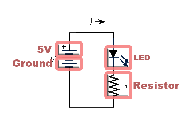
The following is a simple LED circuit drawn as a schematic diagram. The component are circled in pale red and labelled:
If we want to use the Arduino to turn the light on and off, we can modify the above schematic diagram to the following:
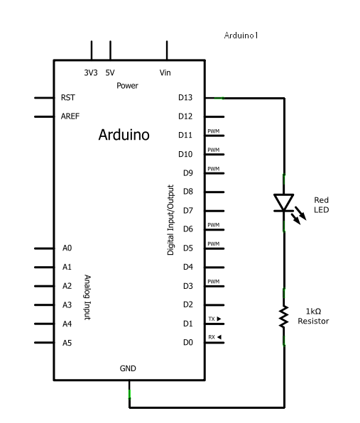
This circuit calls for two pieces of hardware in addition to the Arduino, a red LED and a 1000Ω resistor. LEDs are the lights in your kit, and a red one should be easy to find, so take one out now. The resistor might be a bit trickier because resistors are labeled with stripes instead of numbers. So let's learn a bit about resistors so we know why they are used, and can pick the right one for the diagram.
Resistors are one of the most common electronic components so let's explore how they work.
Unlike the LED and some other electronics components, resistors can be connected in any direction - they don't have positive and negative leads.
Resistors reduce the flow of electricity, or current, in a circuit. All electrical components resist to some degree, even wires, but resistors are designed specifically for that purpose.
When you complete a circuit that has no resistance, current will flow through it as fast as the power source can provide it. If you have a source with a lot of available power this results in heat which may burn you or melt and ruin electrical components. A common metaphor for electrical current is water in pipes. If you have a pipe that is open to air, this is a bit like a circuit that is connected to ground. If you have a high pressure source and a wide pipe then a lot of water will flow through the pipe to air. If there is a narrow spot in the pipe somewhere this will slow the water and less water will flow out of the pipe where it opens to air. Sometimes you want a lot of water to flow to air, as in a fire hose. Sometimes you want a little water to flow to air, as in a water fountain. The same goes for electricity. Sometimes you want a lot of current because you are driving a motor. Other times you want only a little because you are driving a small LED.
Ohm's law expresses the relation between voltage, current and resistance:
V = IRwhere:
Resistors are used to:
The last point is kind of complicated, but lots of interesting
circuits make use of this voltage adjustment property. In the LED
circuit, the resistor is protecting the LED.
Resistance to current is measured in ohms. Ohms are represented with the greek symbol Omega (Ω). You saw this symbol in the circuit schematic above. When a circuit diagram calls for a resistor with a certain resistance it is important to get the right one.
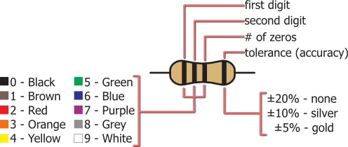
Resistors come in a very wide range of values. They are also typically very small. So rather than trying to print a resistor's value directly on its case, a color coding system is used. This same color system is sometimes used for capacitors too, so it's a good idea to learn it. The system goes like this:
The first three bands express ohms in scientific notation. The number represented by the first two bands is multiplied by 10 to the power of the number on the third band. Another way of thinking of this is the number represented by the third band represents how many zeros follow the numbers represented by the first two bands.
The last band represents the margin of error in the resistance value.
So, what is the smallest possible resistance value in this system? (hover over the line below to reveal the answer)
00x100Ω or 0Ω
What is the largest? (hover over the line below to reveal the answer)
99x109Ω or 99,000,000,000Ω
Here are a few examples of resistors I have laying around. See if you can correctly identify them from their colors. Hover over the lines below each resistor to reveal the answer.
 green blue brown gold 5 6 1 5% — 56x101Ω — 560Ω ±5% |
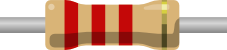 red red red gold 2 2 2 5% — 22x102Ω — 2,200Ω ±5% |
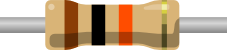 brown black orange gold 1 0 3 5% — 10x103Ω — 10,000Ω ±5% |
You need the 1000 Ohm resistor for the LED circuit. Find the correct one in your kit.
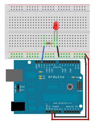
Now that we have our components picked out, let's take another look at how they are supposed to be connected:
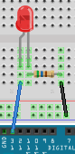
Notice that the schematic shows the circuit starting at pin 13 which can be controlled to turn the LED on and off. GND represents ground and is not actually in that place on the board (but it makes a nice diagram). More realistically, your board will look like this:
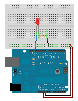
You can put the resistor on the other side of the light and you will still get the same results.
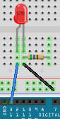
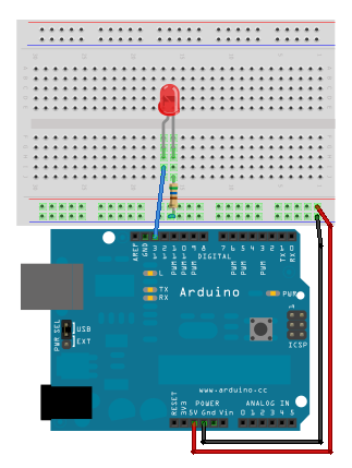
Or, you can save one wire by turning the resistor 90° to get a layout that looks like this:
Now, it's your turn to build this circuit. Try one or all of them.
Something to watch for:
Aside: These breadboard diagrams were created using Fritzing. This is a great way to document what your breadboards look like when you are working on a project. To get Fritzing: http://fritzing.org/download/ |
Under the File menu, choose: Examples | Basics | Blink.
This is the code from last week:
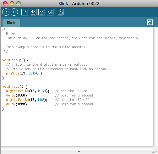
Let us try running the code:
The LED part of your circuit might look like this:
The resistor is used to prevent damage to the LED. It reduces the current coming from the output pin to a level that is safe for the LED. Technically, it is not needed in this circuit because pin 13 has a resistor built in. However, If you use an LED with any other output pin you should use a resistor.
Adjust your wires so the resistor is no longer in the circuit .
What do you notice?
You can use different values of resistors to adjust the brightness of your LEDs. For the 5V Arduino source and the LEDs in your kits, resistors from 300Ω to 10,000Ω are safe and allow a wide range of brightness levels.
How do you know what values of resistor to use with an LED? The answer is a bit complicated and involves Ohm's law. It depends on the voltage of the power source and the type of LED you are using. Click here for a web page that has a good discussion of the topic.
A sketch is the fancy name that Arduino uses to mean a program or code. It is written in text—just like a document. For those of you who would like to know, sketches are C/C++ based. When you sucessfully Compile/Verify the program, it is translated to Arduino machine-language, which is not human readable. So, let us look at the Blink program in detail:
/*
  Blink
  Turns on an LED on for one second, then off for one second, repeatedly.

  This example code is in the public domain.
 */

void setup() {
  // initialize the digital pin as an output.
  // Pin 13 has an LED connected on most Arduino boards:
  pinMode(13, OUTPUT);
}

void loop() {
  digitalWrite(13, HIGH);   // set the LED on
  delay(1000);              // wait for a second
  digitalWrite(13, LOW);    // set the LED off
  delay(1000);              // wait for a second
}
You may notice that many of the lines have a semi-colon (;). Semi-colons are the way of indicating the end of a statement; similar to how we use a period (.) to end our statements. The semi-colon is important--if you forget one, then your code will not Compile/Verify.
Comments are like reminder notes of what is going on in the code. Comments are ignored by Arduino, but are a highly recommended addition to your code. Comments remind you what you have done and make it easier for someone else to understand what your code is doing.
There are two forms of comments demonstrated in the code above:
We can change the above code to have a variable called ledPin. Notice how instead of using 13 everywhere, you now use ledPin. Why would we want to do that?
/*
  Blink
  Turns on an LED on for one second, then off for one second, repeatedly.

  This example code is in the public domain.
 */
int ledPin=13;
void setup() {
  // initialize the digital pin as an output.
  // Pin 13 has an LED connected on most Arduino boards:
  pinMode(ledPin, OUTPUT);
}

void loop() {
  digitalWrite(ledPin, HIGH);   // set the LED on
  delay(1000);              // wait for a second
  digitalWrite(ledPin, LOW);    // set the LED off
  delay(1000);              // wait for a second
}
You will notice that:
int ledPin=13;
is a declaration to say "that we would like to create a box named ledPin and put the number 13 in that box." (http://www.ladyada.net/learn/arduino/lesson2.html). Notice that int indicates that the type of box is an integer. After the declaration, you use ledPin where you had 13 before.
Try: Adding the variable, then change the 13 to a 10. What else do you have to change in order to get your light to blink?
We will be looking at procedures in detail in a later lab. For now, you can interpret procedures as a collection of statements that are grouped by a task. To mark the beginning and ending of the grouping, an opening curly bracket ( { ) and closing curly bracket ( } ) are used respectively instead of a semi-colon (;). Arduino expects two procedures in every program:
We will look at the statements within these two procedures in detail in the next two subsections.
Remember, the statements within setup are executed once at the beginning of your program. In our example code, there is only one statement within this procedure:
pinMode(ledPin, OUTPUT);
This statement tells Arduino to "setup" the ledPin (originally pin 13) as an OUTPUT pin. OUTPUT means that a voltage will be sent out from the pin, thus controlling our LED. The other option (not used in this lab) is INPUT, which means that a voltage will be read from the pin. Any of the digital or analog pins can be used for output. Pins 0 and 1 should be avoided in most projects because they are used to communicate with the computer (TX and RX). The analog pins, A0 to A5, can be referred to by those names or as pins 14 to 19 respectively when you use the pinMode statement.
Remember, the statements within loop are executed over and over again forever. The guts of what we want our program to do are inside this procedure. The two major statement types are :
The digitalWrite command will only set your LED to on or off. If you want to set your LED to different brightnesses you can use analogWrite. It works a lot like digitalWrite, except you use a number from 0 to 255 to indicate brightness. For example:
analogWrite(10, 128);
would make a LED on pin 10 glow at half brightness. It does this by switching the output pin between HIGH and LOW within a short period of time. The higher the number you give to analog write, the longer the output is high relative to low. If you use 0, the pin is always LOW, and if you use 255, the pin is always HIGH. This technique is called PWM (Pulse Width Modulation) and it only works on the PWM pins: 3, 5, 6, 9, 10, and 11.
Well, you now know how to make a light blink.
What can we do with a blinky light? How about making a message with Morse Code?
You have the choice of making SOS or the initials of your name.
Please use any pin other than pin 13 for this exercise.
Morse code is made of a combination of 5 elements:
| Dots (or Dits) | 1 unit of time |
| Dashes (or Dahs) | 3 units of time |
| Pause between a Dot or a Dash | 1 unit of time |
| Pause between Letters | 3 units of time |
| Pause between Words | 7 units of time |
Let's say that 1 unit of time is 240 milliseconds. But it could change so make this a variable (called uTime). At the top of the code, you will have:
int uTime=240;
Then when you are using delay, you can write:
delay (uTime);
or
delay(3*uTime); //if you want 3 units of time
To make SOS, the S is three dots and the O is three dashes. To break this down by timing:
At the beginning, I said that you would have the choice of making your own initials in Morse code. For your reference, to look up your initials, you can find a Morse code chart here:
http://en.wikipedia.org/wiki/File:International_Morse_Code.svg
Everyone should get some kind of Morse Code message working. You should push yourself by trying one of these challenges.
Beginner: everything you need is in the notes above.
Intermediate: extras are shown below.
Advanced: only experienced programmers who know a C–like language already should try this.